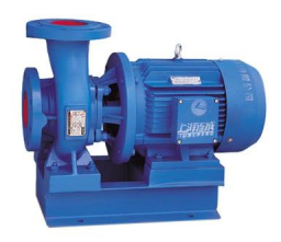
Centrifugal pumps are defined as rotodynamic pumps in which rotating impellers increase the pressure of the fluid. Centrifugal pumps are used to transfer the liquid from one place to another say at a certain height through the piping system. In this case, the mechanical energy of the motor is converted into hydraulic energy by centrifugal force acting on the liquid.
Working Principle of Centrifugal Pumps
Whenever a certain mass of fluid is rotated by any external source, say an impeller in the case of a centrifugal pump, is thrown away from the central axis of rotation which enables liquid to rise to a higher level. The mechanical energy of the motor is converted into hydraulic energy by centrifugal force acting on the liquid
Parts of Centrifugal Pumps
Centrifugal pumps consist of the following parts:
Impeller
A wheel with a series of backward curved vanes and at the center of curved vanes, there is an inlet of the liquid and also called the eye of an impeller. That wheel is mounted on the shaft which is coupled with the motor. As the motor rotates, the wheel gets rotated and thus the impeller. This impeller when in rotation force the liquid out due to centrifugal force. Hence, the liquid gets displaced and the space in get vacant in the casing.
To fill that space, liquid rushes in, and then again impeller throughs the liquid out in discharge pipes. The speed of rotation of the wheel imparts kinetic energy to the liquid in terms of velocity which the converted into pressure (potential) energy.
Types of Impeller
There are three types of the impeller which are described below:
- Open Impeller
- Semi-Open Impeller
- Closed Impeller
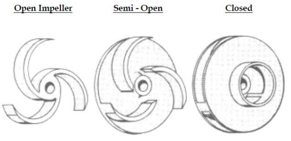
Open impeller
The open impeller is defined as the impeller which has vanes attached to the center Hub or directly mountain on the shaft. There are no surrounding walls or shrouds. That is why this type of impeller is weaker compared to two other impellers. These impellers are generally very easy to clean and used in smaller pumps and used for pumping the contaminated solid type liquids.
Semi-Open Impeller
Semi-pen impellers have vanes mounted in the walls on one side. It is used to transfer lightly contaminated and abrasive liquids and slurries.
Closed Impeller
These impellers have the vanes enclosed by walls on both sides thus providing good strength. These impellers are generally used in large pumps. These impellers are used to transfer the clear liquids. It is difficult to wash them if they get clogged.
Casing
Casin is defined as the Air-tight chamber surrounding the impeller. There are generally three types of the casing which are described below:
- Volute Casing
- Vortex casing
- Casing with guide blades
We will discuss all these one by one:
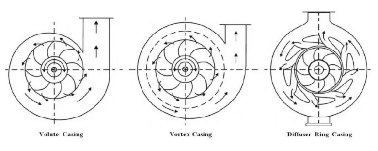
Volute Casing
In the volute casing, the area of the flow increases gradually from the eye of the impeller to the delivery pipe. The increase in the area decreases the velocity of the flow and a decrease in velocity increase the pressure of the flow.
Vortex casing
In the case of Vortex casing, the circular chamber is provided between the volute chamber and impeller. Vortex casing helps to increase the pump efficiency by reducing the formation of eddies.
Casing with guide blades
In this case, the impeller is surrounded by a series of guide blades that are mounted on a ring called a Diffuser. It is designed in such a way that water that is leaving the impeller, enters the guideways without shock.
Suction Pipe
The suction pipe is the pipe that is mounted with the help of a flange at the inlet of the pump. One end is connected to the eye and the other is dipped in a liquid.
Delivery pipe
The delivery pipe is the pipe that has one end connected to the eye, and the other to the overhead tank or directly send for application on the machine.
Foot valve
A foot valve is provided at the suction of the pipe at the open end and is immersed in the liquid. The foot valve is also called a check valve. This foot valve allows liquid to move in one direction only. When the pump is switched on, the spring in the foot valve is lifted up and allows the water to go in the suction pipe. When the pump is made off, this foot valve comes to its original position by spring force and does not allow the liquid to go back into the tank. A strainer is generally there with the foot valve to prevent the foreign matter from going inside the pump.
Strainer
As discussed Foot valve, the strainer is a part that is used to prevent the entry of foreign particles/material into the pump. If it is not there, foreign particles might go inside the pump and can damage the casing and impeller.
Working of Centrifugal Pumps
Whenever a certain mass of fluid is rotated by any external source, say an impeller in the case of a centrifugal pump, is thrown away from the central axis of rotation which enables liquid to rise to a higher level. The working of the Centrifugal pump is as follows:
- First of all, the delivery valve is closed and the suction pipe, casing, and a portion of the discharge pipe are primed with liquid so that no air is left in the pipe casing.
- Then, the Motor is started and a strong suction is created at the eye of the impeller.
- At that time delivery valve is opened.
- Now, liquid flows through the eye of the impeller and out from the casing.
- The mechanical energy of the motor is converted into hydraulic energy by centrifugal force acting on the liquid.
- The liquid is then lifted to the required height.
- Then, the delivery valve should be closed so that liquid stays in the pipe or reservoir on the top of the discharge pipe. Otherwise, if there is leakage of liquid through the suction line, then the discharge line or reservoir will get empty, and then it would be difficult to lift the water until primed.
Learn more at Google
Heads of Centrifugal Pumps
The centrifugal pump has the following types of head
- Suction Head
- Delivery Head
- Static Head
- Manometric Head
Suction Head
The suction head is defined as the vertical distance between the eye of an impeller and the level of the sump. It is also called a suction lift and is denoted by ‘hs‘
Delivery Head
The delivery head is defined as the vertical distance between the eye of an impeller and the level where water is delivered. It is denoted by ‘hd‘
Static Head
The static head is the sum of the suction head and delivery head. It is given by
Hs = (hs+ hd)
Manometric Head
The manometric head is the head against which the centrifugal pump has to work.
Efficiency of Centrifugal Pumps
Volumetric Efficiency (ηv)
ηv= Liquid discharge per second from the pump / Quantity of liquid passing per second through the impeller
= (Q+q)/Q
Where,
Q = Actual liquid discharged at the pump outlet per second
q = Leakage of liquid per second from the impeller
Mechanical Efficiency (ηm)
ηm= Power at impeller / Power at the shaft
Overall Efficiency
Overall Effieciency= Output power of Pump / Input power of the pump
Also, Read What is Hydraulics and Hydraulic components
Frequently Asked Questions
What are wear rings in centrifugal pumps?
The Centrifugal pump has a stationary wear ring on the casing and a rotating wear ring on the impeller. This wear rings clearance is very important in terms of efficiency.
What are the types of Centrifugal pumps?
There are three types of centrifugal pumps:
Radial
Axial
Mixed flow
What are the parts of a centrifugal pump?
The centrifugal pump has the following parts:
Impeller
Casing
Suction Pipe
Delivery Pipe
Foot Valve
Strainer
Shaft
Bearing
Seals