An XNOR (exclusive-NOR) logic gate is a digital logic gate that implements an exclusive NOR function. It’s essentially the complement of the XOR gate. Here’s an in-depth look at the XNOR gate:
Functionality
- The XNOR gate performs a logical operation on two binary inputs and gives a single binary output.
- The output of an XNOR gate is true (1) if and only if both inputs are the same (both 0 or both 1).
- In terms of Boolean algebra, the XNOR operation can be represented as A⊕B, where ⊕ denotes the XNOR operation.
Truth Table
The truth table of an XNOR gate is as follows:
| Input A | Input B | Output (A XNOR B) |
|---|---|---|
| 0 | 0 | 1 |
| 0 | 1 | 0 |
| 1 | 0 | 0 |
| 1 | 1 | 1 |
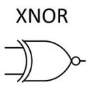
XNOR Symbol
The symbol of an XNOR gate is similar to that of an XOR gate, but with an additional curve on the output side, indicating the negation (complement) of the XOR operation.
Logical Expression
The logical expression for an XNOR gate can be derived from the truth table. The simplest form of the expression for a two-input XNOR gate is �⊕�‾A⊕B or �≡�A≡B, where ≡≡ denotes logical equivalence.
Realization Using Other Gates
An XNOR gate can be constructed using basic gates like AND, OR, and NOT. For example, an XNOR gate can be realized using two NOT gates, two AND gates, and one OR gate.
Applications
- XNOR gates are commonly used in digital circuits where equality checking is required.
- They are essential in error detection and correction algorithms.
- XNOR gates are also used in various logical circuits where a specific output pattern is needed based on the similarity of inputs.
Diagram
To illustrate the XNOR gate symbol, truth table, and a basic circuit diagram, a visual representation for better understanding is given below. Let’s start with the diagram.

Here is the diagram showing the symbol of an XNOR logic gate, its truth table, and a simple circuit diagram. This visual representation includes:
- The Symbol of the XNOR Gate: It resembles an XOR gate with an additional curve on the output side, indicating the negation of XOR.
- The Truth Table: It lists the inputs A and B along with the output A XNOR B, showing the results for all combinations of inputs.
- A Simple Circuit Diagram: This illustrates how an XNOR gate can be constructed using basic gates (AND, OR, NOT). The diagram demonstrates the arrangement of two NOT gates, two AND gates, and one OR gate, with logical connections to form the XNOR functionality.
This diagram helps in understanding how an XNOR gate functions both symbolically and practically in circuit design.
- XNOR Gate Truth Table: The truth table for an XNOR gate is a representation of its output for all possible input combinations. An XNOR gate outputs a 1 when both inputs are the same and a 0 otherwise.Input AInput BOutput (A XNOR B)001010100111
- XNOR Gate Symbol: The symbol for an XNOR gate is similar to the XOR gate, which is a rectangle with a curved line at the input side and a small circle or “bubble” at the output side, indicating the inversion or negation of the XOR function.
- XNOR Gate Boolean Expression: The Boolean expression for an XNOR gate is the negation of the XOR function. For two inputs A and B, it can be written as �⊕�‾A⊕B or �≡�A≡B, signifying that the output is true if A and B are both true or both false.
- XNOR Gate Using NAND Gate: An XNOR gate can be implemented using only NAND gates by connecting them in a specific configuration. You would need four NAND gates to create an XNOR function. The first two gates would take the inputs A and B and their negations, the third would be the NAND of the outputs of the first two, and the fourth would NAND the output of the third gate with itself.
- XNOR Gate Using NOR Gate: To create an XNOR gate using NOR gates, you would need to arrange the NOR gates in a particular configuration. Typically, this would involve a combination of NOR and NOT functions, which can be built using NOR gates since the NOR gate is a universal gate.
- XNOR Gate Equation: The XNOR gate equation can be written in sum-of-products form as: (�⋅�)+(�‾⋅�‾)(A⋅B)+(A⋅B) This represents the logical equivalence function, which is true when A and B are both true (1) or both false (0).
- XNOR Gate Minecraft: In the game Minecraft, logic gates can be created using redstone. An XNOR gate can be built using a combination of redstone torches, dust, repeaters, and blocks to control the flow of redstone signals in such a way that it mimics the function of an XNOR gate.
- XNOR Gate IC Number: Integrated circuits (ICs) that perform the XNOR function are available and have specific part numbers depending on their logic family. For example, in the TTL logic family, the 74LS266 is a quad 2-input XNOR gate.
- XNOR Gate Circuit Diagram: A circuit diagram of an XNOR gate would illustrate the internal connections of the basic gates (AND, OR, NOT) or NAND/NOR gates required to implement the XNOR function. It visually represents how inputs are processed to produce the output.
- XNOR Gate IC: An XNOR gate IC is a chip that contains the XNOR gate function in integrated form. It can come in different configurations, such as dual 4-input, quad 2-input, etc. The pin configuration will vary depending on the specific IC used.
Each point relates to various aspects of the XNOR logic gate, from its basic properties to its implementation in both digital circuits and simulations like Minecraft.
1 thought on “Understanding XNOR Logic Gate: Diagrams, Truth Tables”